FOR TIPS, gUIDES & TUTORIALS

subscribe to our Youtube

GO TO YOUTUBE

14455 questions

17168 answers

28195 comments

0 members

We are migrating to our new platform at https://community.teltonika.lt. Moving forward, you can continue discussions on this new platform. This current platform will be temporarily maintained for reference purposes.
0 votes
420 views 3 comments
by anonymous
Hello everyone.

I have a RUT955 and would like to use the Power socket I / O pins.

All right with the entrance, I can get it read.

But I can't find information on how to use pin 4 (output) to drive a relay.

I tried to read with a tester between pin 4 and a mass by manually setting the output status ... but it never changes and I don't know why.

I can't find explanatory diagrams, can you help me please? Thanks

1 Answer

0 votes
by anonymous
Hi,

You should find all the information you need here: https://wiki.teltonika-networks.com/view/RUT955_Input/Output

EB.
by anonymous
Hi, I had already seen those pages you kindly indicated to me but unfortunately there are no examples to use the power connector output (pin 4 of the 4pin connector) from which, as I said, I can detect a voltage of just 0 , About 5 volts also by commanding the output from the web gui high.

I would need an example diagram for that specific door to understand if I am doing something wrong.

Thank you
by anonymous

Could you check if this changes the status of your 4PIN output?

gpio.sh invert DOUT1

gpio.sh get DOUT1

EB.

by anonymous

Sorry for the delay in replying.

Thanks for the suggestion, but what I really need is to have an example diagram to connect a relay to the output (pin 4) of the Power Socket connector.

If the example of the open collector output (pin 3,4,8) is well explained here
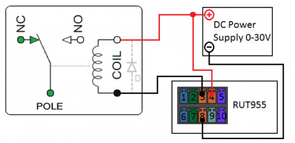
I miss it, and I don't find in the wikis or in the diagrams a practical example for the output port (pin4) of the power connector, considering that pin 3 is an input and pin1,2 are power supply.

I hope I have explained.

Thanks again