FOR TIPS, gUIDES & TUTORIALS

subscribe to our Youtube

GO TO YOUTUBE

14455 questions

17168 answers

28195 comments

0 members

We are migrating to our new platform at https://community.teltonika.lt. Moving forward, you can continue discussions on this new platform. This current platform will be temporarily maintained for reference purposes.
0 votes
713 views 6 comments
by anonymous

Hi everyone,

I actively use a 2 wire loop powered 4 - 20 mA transmitter (INOR R202) connected to a TRB141 for both Analog Voltage (across 250/500/1000 ohm resistor) and Analog Current Loop and both work very well. 

With the new RUT955 firmware version (RUT9_R_00.07.01.2), the WebUI now has an option for Analog Current Loop too. But when I connect my 4 -20 mA transmitter, the reading only shows 18.x mA and never changes. The Analog Voltage function works fine.

I am not sure to what the issue could be. My speculation is that the WebUI shows the Analog Current loop function, but the hardware might not support Analog Current directly. 

Can anyone confirm the same issue? Or give me ideas to why this could happen?

Regards!

1 Answer

0 votes
by anonymous

Hello. I can confirm that the RUT955 with Firmware can measure current as expected.

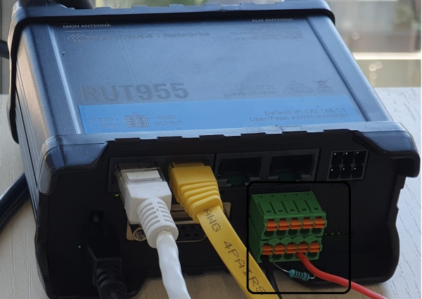
The Lab setup consisted of a small 1/8W resistor, low precision 1 Kohm

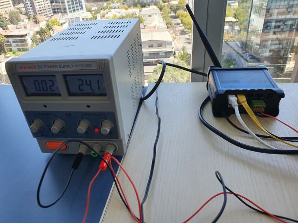
A regulable power supply 0-30V

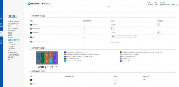
The RUT955 detected current with no problem in all the range from 0 to 24.1V at wich point it measure 20mA. 

Please note that the resistor was calculated to provide 20mA at 20V but we didn't took in account the uncertainty of the non precision resistor and the temperature of the lab

Attached you will find the values obtained and the Lab Setup.

Please make sure that the analog input never exceed 30V. Otherwise it will get damage at some of the components that could lead to such failure.

If you think that the device is damaged from factory. Please feel free to contact your local distributor to request a guaranty procedure.

by anonymous

Hi JPTeltonika, thanks for your explanation just need some extra clarification. From your post please confirm points below so we can fully understand difference for measuring 4-20mA Current between TRB-141 and RUT-955. 

  1. TRB-141 can measure 4-20mA current directly without needing external resistor if you select this option on GUI. 
  2. RUT-955 cannot measure current directly. It measures only voltage and therefore requires external resistor to convert current to a suitable voltage range. .. 
  3. Confusion is that Web GUI for RUT 955 and TRB141 both provide option of Analog Current Loop (see screen shot below for 955 showing current loop option which is same as TRB141 so a user would conclude that 955 does not need external resistor- ie it works same way as 141.  
by anonymous
TRB-141 can measure 4-20mA current directly without needing external resistor if you select this option on GUI.

Correct. TRB141 activates an internal current loop while RUT955 in effect needs that shunt resistor.

The need to maintain the current loop for RUT955 is for compatibility and standardization reasons
by anonymous
OK @jpteltonika - The GUI on RUT-955 is confusing as it gives user the option of choosing Current or Voltage - just like for the TRB-141.

Can we suggest to Teltonika that they should update 955 so it has internal shunt resistor same as TRB?
by anonymous
Hello.

Sure, we are on process to send the Requirement to RnD
by anonymous

Hello,

Regarding the analog current loop not functioning properly with RUT955 devices - this is a known issue from software side - Analog Current Loop (6,9 pins) does not trigger any actions on firmware version RUT9_R_00.07.01.2. It is planned to be patched up in firmware version 7.2. 

Regarding the hardware changes - there are currently no plans to implement a built-in resistor. Just like jpteltonika suggested, an external resistor must be used to measure the current. This process is described on our wiki page here:

https://wiki.teltonika-networks.com/view/RUT955_Current_Measurement_with_Analog_Input

Best regards,

Tomas.

by anonymous
My experience too.
I connect loop powered device

Ain voltage is 9.6V

955 measures 8mA (25%) in current mode.  Bzzzzzt could not possibly be 8mA @ 9V
when switching to voltage input mode in online screen, 955 reads 9.9V  not great accuracy

It is clear that current mode does not switch to low-resistance mode.
The online documentation should be updated to reflect this fact.
In the absence of corrective documentation, an input which switches between voltage and current can be presumed to do the proper hardware monkeybusiness.
Even knowing that there is no resistor, it would be good to know what resistance the 955 is expecting as the dropping resistor.
Typical values would be 100ohms, 250 ohms.  Maybe in unusual circumstances 500 ohms. But 1000 ohms is way out to lunch.

Is it reasonable to assume that when switching to current mode, the 955 will do the math correctly ?
Or do we just treat it as a voltage device and do our own math ?

On the topic of scaling, what is the easiest way to do scaling on the values obtained from local hardware or from

modbus-connected hardware before uploading to a portal ?  It's kinda clunky to do that stuff in shell-scripts ?