FOR TIPS, gUIDES & TUTORIALS

subscribe to our Youtube

GO TO YOUTUBE

14455 questions

17168 answers

28195 comments

0 members

We are migrating to our new platform at https://community.teltonika.lt. Moving forward, you can continue discussions on this new platform. This current platform will be temporarily maintained for reference purposes.
0 votes
7,202 views 6 comments
by
I need to use the RS232 port (/dev/ttyS0) to read raw data from another device. However, the port is configured as a console  port, so it require login when trying to send data that port from outside. Anyone has an idea ?

Thank you !

1 Answer

+1 vote
by anonymous
Hello,

Have you tried to use other RS232 serial type? Instead of using "Console", try "Over IP", this allows directly connect to router and send commands and read data. For more information check Teltonika Wiki: https://wiki.teltonika.lt/view/RS232/RS485#Over_IP
by

Thank you for your response, 

I have tried the Over-IP mode, but no results.

To be clear, I am using a solar charger with an RS232 port outputting the battery status. I am using the Teltonika to read data from that port. 

FYI, the Teltonika RS232 is working good with laptop, on console and over-IP modes. the problem is the Teltonika-solar-charger serial port communication. If you can read this answer from the solar charger manufacturer, maybe it make sense to you.

The DTR signal (pin 4 on the DB9 connector) and/or the RTS signal (pin 7 on the DB9 connector) must be driven high to power the isolated side of the the interface. How to program the DTR and RTS differs between used operating systems and hardware. Please note that most RS232 drivers are inverting so the logic level of the DTR must be programmed to zero in most cases. When one of those pins is not driven high, you will not be able to receive data!

Background: the “VE.Direct to RS232 interface - ASS030520500” provides galvanic isolation between the VE.Direct product and the host (your computer/PLC/etc). The VE.Direct side of the PCB is powered from VE.Direct. And the RS232 side takes its power from the DTR and RTS pins.

When using an external power supply to power DTR or RTS, the minimum voltage is 5V, and maximum is 12V. Note that it is normally not necessary to use an external power supply for this: normal serial ports will either automatically drive DTR or RTS high. And if not that, than you can control those pins to be high from within the software.

Does it make sense to you ? In my head, on the hardware level, it is standard connection... 
by anonymous
by anonymous
Looking from electrical side everything is ok, since you can connect to laptop.

Can you provide more information about your system? I.e. solar charger model, system topology, router troubleshoot file where you have configured rs232 mode "over IP".
by anonymous

Hi Thomas, 

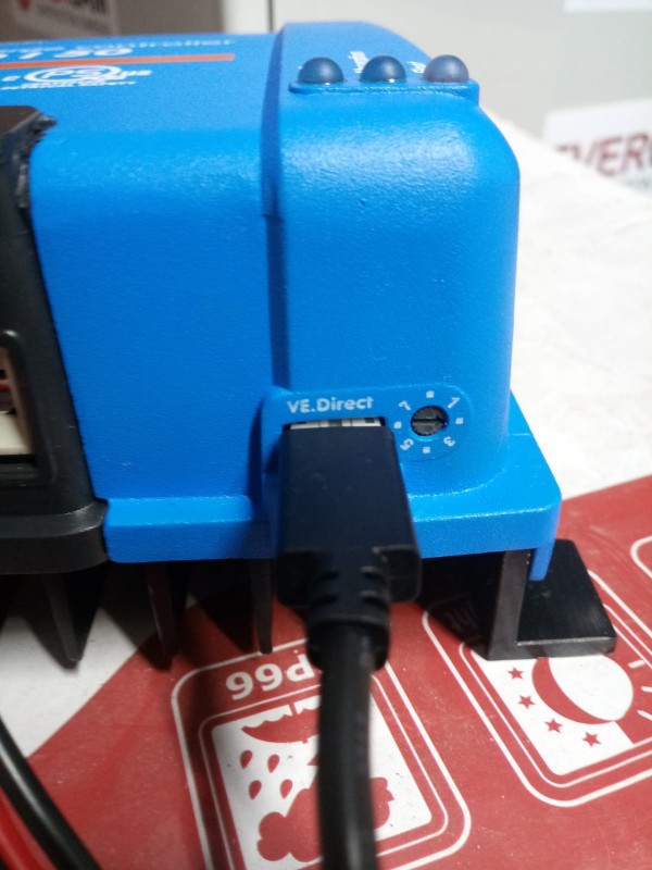
here is the solar  controller we are using https://www.victronenergy.com/upload/documents/Datasheet-BlueSolar-charge-controller-MPPT-100-30-&-100-50-EN.pdf.

here is the port from the solar controller: 

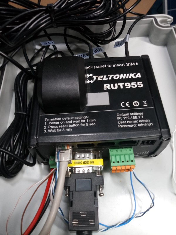
And here is the connection on the teltonika side :

here is the ouput of  dmesg | grep tty :

125.720000]  ar934x-hs-uart : ar934x_hs_uart_get_scale_step() clk:40000000 scale:0x0022 step:0x044D baud:9600 min_diff:0

[ 4139.460000] nf_conntrack: automatic helper assignment is deprecated and it will be removed soon. Use the iptables CT target to attach helpers instead.

[ 8395.730000]  ar934x-hs-uart : ar934x_hs_uart_get_scale_step() clk:40000000 scale:0x0022 step:0x044D baud:9600 min_diff:0

root@Teltonika-RUT955:~# dmesg | grep tty

[    0.000000] Kernel command line:  board=TLT-RUT900 console=ttyS0,115200 rootfstype=squashfs,jffs2 noinitrd lpj=1370112 quiet loglevel=3

[    0.460000] console [ttyS0] disabled

[    0.480000] serial8250.0: ttyS0 at MMIO 0x18020000 (irq = 11, base_baud = 2500000) is a 16550A

[    0.480000] console [ttyS0] enabled

[    0.480000] ar934x-hs-uart.0: ttyATH0 at MMIO 0x18500000 (irq = 14, base_baud = 2500000) is a AR934X UART

[   13.010000] cdc_acm 1-1.1:1.0: ttyACM0: USB ACM device

[   20.980000] usb 1-1.3: GSM modem (1-port) converter now attached to ttyUSB0

[   20.980000] usb 1-1.3: GSM modem (1-port) converter now attached to ttyUSB1

[   20.980000] usb 1-1.3: GSM modem (1-port) converter now attached to ttyUSB2

[   20.980000] usb 1-1.3: GSM modem (1-port) converter now attached to ttyUSB3

by anonymous
Gathering the full story in 1 document here:

https://docs.google.com/document/d/1zDsYI2sL7xeiJ_fKi_qMTfu0L19nX3EFjaZLCprjhRM/edit?usp=sharing

We could private message you a remote login or teamviewer session?
by anonymous
Router and VE cable both are DCE devices, they both need to pull high DTR and RTS pins up to establish communication.

To overcome this, one possible solution is to modify cabling, if you are not planning to use flow control, connect router CTS (pin 8) to VE cable DTR (pin 4) and router DSR (pin 6) to VE cable RTS (pin 7), this will pull up VE cable DTR and RTS and data will start to flow.