As far a I can see there is clearly a major issue with the implementation of RS485 on RUT955. I've tried several routers and the problem is still there. After probing the data lines to the HVD73 chip my impression is that there is an error with the implementation.
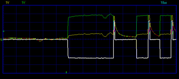
This is what I get on the oscilloscope when looking at the RS485 data lines from the RUT955. CH1 (yellow) is D_N pin (driver negative) and CH2 (green) is D_P (driver positive). Ground reference is router chassi ground. White is CH1-CH2 (math). RS485 signal levels require 200 mV difference between D+ and D- for detection of high/low level. This means that "high" levels are never detected. Baud rate is set to 115200 which means shortest pulse is about 8 us.
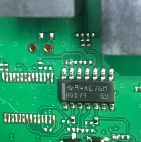
To investigate this further on I took a look at the input pins to the HVD73 chip, the RS-485 tranceiver inside the RUT955.
The interesting pins here are pin 4 DE (driver enable high) and 5 D (driver data input). Looking at those in the oscilloscope when sending data:
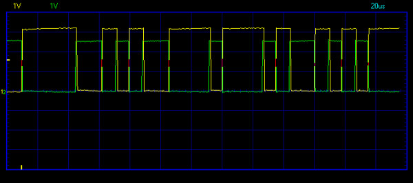
Those lines are inverted with respect to one another which means that driver enable (DE) is only high when data (D) is low. This means that it is impossible to recieve any data (since all the "high" levels are omitted).
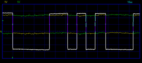
For reference here is a "normal" RS485 data transfer using a RS485 USB serial modem connected to a computer:
I've not been able to figure out if the DE line is somehow connected to a GPIO pin on the Atheros SoC. If so this is maybe a driver related issue within RutOS? And software setting or registry write that can bring this line "high"? For this particular use we have a full duplex single master RS485 network which means that leaving the driver on (=DE high) is not a problem.
So has anyone got RS485 working from RUT955 batch 081? From the pcb image above you can see that the termination resistor and the jumper is missing. Is RS485 support removed? If so why is the transciever still there?
