FOR TIPS, gUIDES & TUTORIALS

subscribe to our Youtube

GO TO YOUTUBE

14455 questions

17168 answers

28195 comments

0 members

We are migrating to our new platform at https://community.teltonika.lt. Moving forward, you can continue discussions on this new platform. This current platform will be temporarily maintained for reference purposes.
+1 vote
1,184 views 1 comments
by anonymous

Hi

I have a TRB245 (FW TRB2_R_00.02.06.1) that I'm trying to interface to a Modbus slave using RS485.

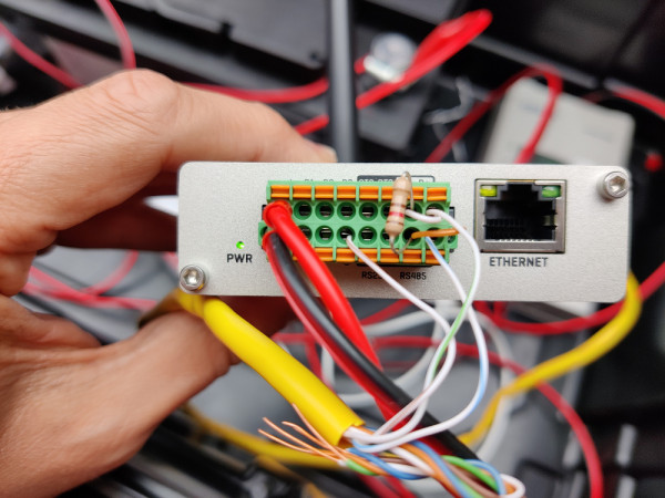
The slave device is an EPEVER solar charge controller that I have worked with previously. I've designed a PCB for an interface to it before, so I know the RS485 settings and wiring, and I know that the unit works. This is a two-wire device, so I've bridged the D+ and R+, and D-/R- connections. I also have a 120R terminator resistor in place. I believe I've wired up as per the wiki page, here's the connector:

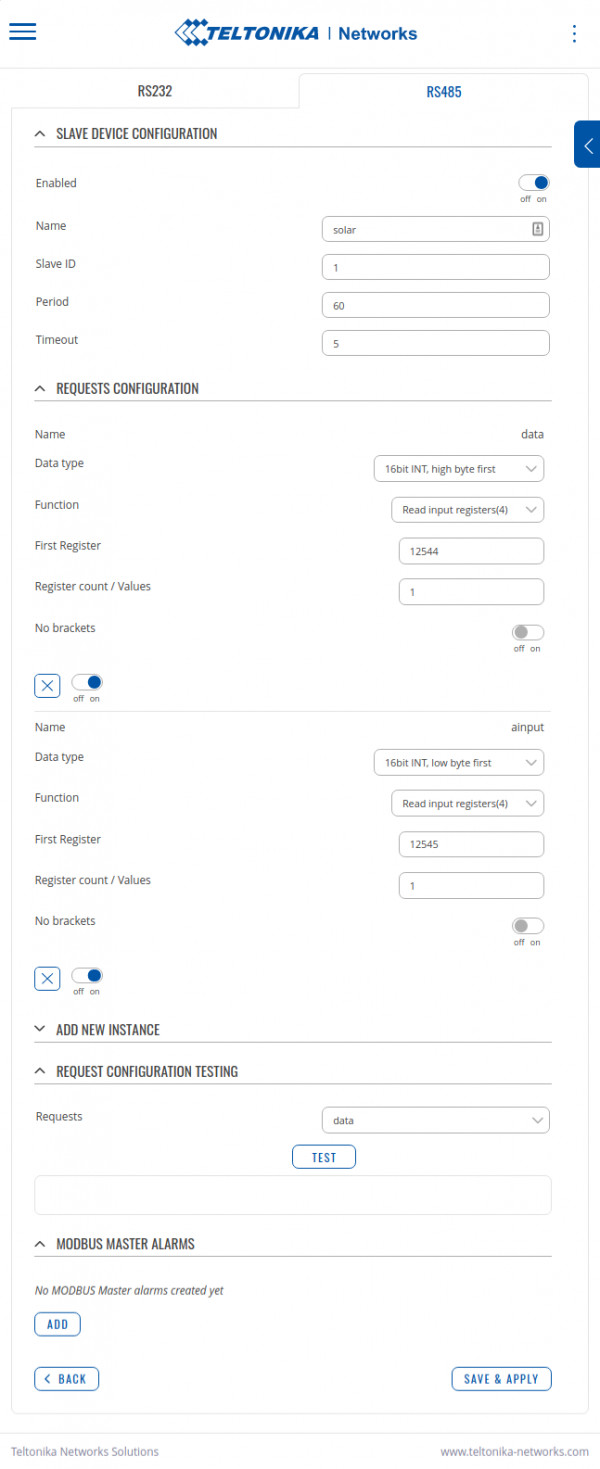
I've configured the TRB245 Modbus/RS485 settings, and added a couple of registers that I would like to query, but unfortunately no joy. When trying to test the "requests" I get the message: "No response from slave device, check wiring and configuration".

Here are the config pages:

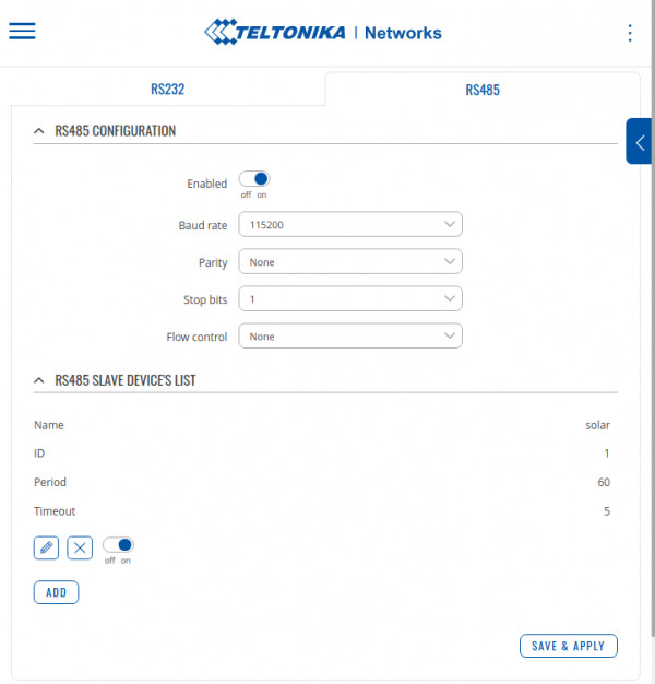
The other RS485 service is disabled.

What have I missed?

Cheers,
Al

5 Answers

0 votes
by anonymous
sorry for my english  :P

when i was doing that i too had tooooo manyyyy problems so i used  2 converters

485 to 232 and a usb to 232 and

i used this for check the comunicacion with the same equipmen (a flowmeter )  and a plc, so when i discovered the question (on modbus)for the values who i was trying to look then started to check how modify the programation of the rut955 for do the same quiestion

in my case i had to add 1 unit to the first register (if my first register is 25 i use 26) and put a 2 into the register count (i dont know why ) and my data was 32bits float 3,4,1,2

so  you can try this if you dont have other answer
by anonymous
Thanks for your suggestions.

I'm pretty sure my settings are right, my charge controller uses 16bit register values for these parameters, so I think I'm right in the addresses and count settings. I have tried a few things with these settings but still nothing.

I think I'll have to get the oscilloscope on it next week!
0 votes
by anonymous
0 votes
by anonymous
0 votes
by anonymous
0 votes
by anonymous

I just spent a fair while on a similar problem, trying to get a TRB145 to read an energy meter with a two-wire (A/B) RS-485 connection. To anyone else struggling with this, I'd recommend the following troubleshooting steps:

  1. Just to be sure, check that the device you're trying to read behaves properly and is responsive to another master (e.g. a computer with a USB-to-RS485 adapter). Use this to verify the required parameters for reading, like baud rate, parity, and unit ID. [tip: if you don't know the unit ID of the device you're trying to read, send a request to unit ID 0 - this is akin to a broadcast address; the device should respond and include its unit ID in the response]
  2. If you're using a 4-wire master (a TRB145/245/255) and a 2-wire slave (most devices, it seems), bridge the positive and negative terminals as per Figure 3 of https://www.advantech.eu/resources/white-papers/02cb2f4e-4fb2-4a87-be3b-508325bd61d6 (similar to what's in the Teltonika docs, but actually legible...): 
  3. Try reading the device this way. In my experience, the terminating resistor is often not necessary, unless you have longer cable lengths and/or are using a high baud rate. If your wiring is done correctly, you should get some response back, even if the function code and/or register you're requesting are invalid for the device. Most devices should respond with an exception code in those cases (rather than nothing at all).
  4. If you don't get anything back, try switching the A and B (+/-) terminals around. I've found incorrect polarity to be the most common reason for not being able to read a device. The assignment of A and B to positive and negative seems pretty arbitrary in most cases (in contrast to what the diagram above seems to imply).
  5. As a last resort, you can play around with removing the ground connection, and adding/removing the termination resistor. I don't have a scientific basis for suggesting this; simply the observation that this is what it sometimes takes to get things working.

@eggfriedrice: in your case, the wiring looks correct; the only thing that drew my attention is that the termination resistor is at the "start" of the line rather than the end. I've usually seen it added to the end (furthest from the master), but also seen docs that specify putting it at at the master..not sure if it makes a difference. Would be curious to hear if you ever got it working.