FOR TIPS, gUIDES & TUTORIALS

subscribe to our Youtube

GO TO YOUTUBE

14088 questions

16729 answers

27457 comments

53741 members

0 votes
150 views 0 comments
by

Hello,

(sorry if you have seen this question in another post)

I have seen this link https://wiki.teltonika-networks.com/view/RUT955_Relay_to_Open_Collector_Output.

1-why we need to connect pin 4 ?

2-can we use pin 3&8 same way as pin 5&10 (and cancel pin 4 connection)

3-can I remove the dc power supply in the diagram and take power from the adaptor that comes with the device (9 volt 0.75A written on it) although the pin 3 says "external 0-30 VDC 0.25A" (in this link https://wiki.teltonika-networks.com/view/RUT955_Input/Output ) does this mean that the main adaptor will damage pin 3 if used ?

4-can I connect external relay coil +ve terminal to the main adaptor and the -ve terminal to pin 5 and connect pin10 to the adaptor ground (without using external power supply).

I know that's a lot of questions, sorry for that.

thanks,

1 Answer

0 votes
by

Hello,

I hope an example schematic will help you to understand better the use of the Open collector output.

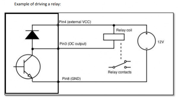
1. Pin4 is used to connect external voltage to drive the connected relay.

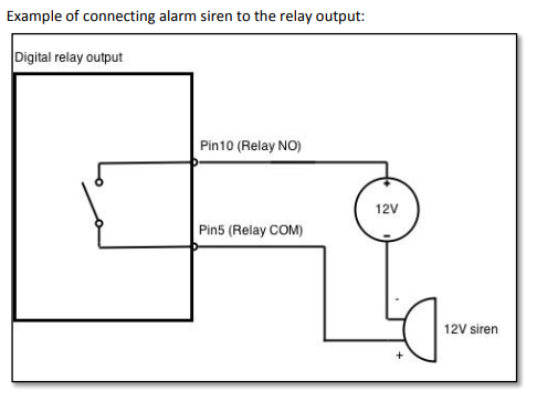
2. Pins 5 (COM) and 10 (NO) are rather output pins of an internal relay to power externally connected devices. A couple of examples below. 5 and 10 contacts also have different electrical ratings.

 3. The parameter you should be looking for on the power supply is voltage. If voltage is sufficient, the circuitry will draw the amount of current it needs, as long as the supply is rated to provide at least that amount, so you should be able to use the power supply the device shipped with. 

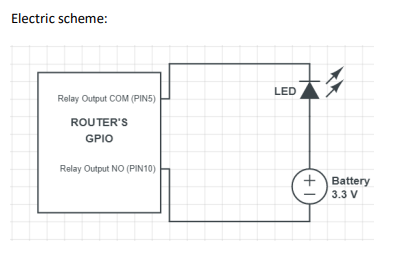
4. Due to internal circuitry your proposed wiring will not work.  

Best regards,